The Original FSM Analysis Problem
This page uses the actual schematic from the reference problem as the anchor. We first analyze the deterministic FSM, then use statistics to study brute-force attempts.
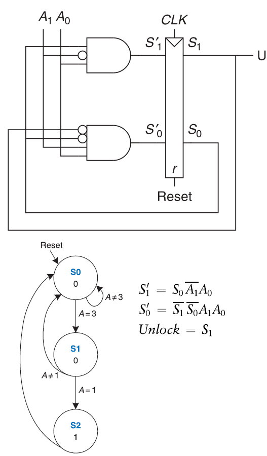
D. M. Harris and S. L. Harris, *Digital Design and Computer Architecture: RISC-V Edition*. Cambridge, MA, USA: Morgan Kaufmann, 2021.
1. Identify signals
Inputs are \(A_1, A_0\). State bits are \(S_1, S_0\). The output is \(Unlock\).
2. Write next-state and output equations
The reference solution derives the next-state logic from the schematic and uses:
\[ Unlock = S_1 \]
3. Build and reduce tables
From the equations, construct next-state and output tables, remove unreachable states, and use don't-care entries where appropriate.
4. Assign symbolic states
The reduced machine is interpreted using symbolic states such as \(S0\), \(S1\), and \(S2\).
5. Draw the state transition diagram
From the diagram we can deduce what the machine is doing (reverse engineering). The Unlock output goes high only when the input is "3" followed by "1".
6. Bridge to probability
Once the valid unlock behavior is known, random attempts become a statistical process:
\[ X = \text{number of attempts until unlock} \]
FSM analysis gives the deterministic behavior. Probability and statistics analyze uncertainty in the attempts.